In this year KubeCon + CloudNativeCon Europe 2023 had more than 10000 members from which 58% has their first time in this global cloud-native conference.
In my second year of diving into cloud-native ecosystem I realised that the knowledge about Networking enables us not only to use the stack in is the distributed computing and communicate Kubernetes, but also increase the awareness of how data transfer between applications is crucial for understanding their performance, security and efficiency.
While I have been relearning some of the concepts back from the Networking days at university, I started documenting the process to share the references and acknowledge the community that our open-source cloud ecosystem is built on- contributors and maintainers!
Thanks to the Marino Wijay and Jason Skrzypek, platform engineers and advocates at Solo.io for their presentation at a fast pace in KubeCon 2023!
Workshop structure:
-
Quick intro to Networking Basics
-
Get to the Gateway
-
It’s not DNS, it can’t be DNS, it was DNS
-
I’m not a teapot- Understanding HTTP Codes and Layer 7
-
Firewalls, Load-balancing, Proxies
-
Container Networking through Networking Namespaces
-
Kubernetes and Networking
Quick intro to Networking Basics
OSI Model is a structure that allows us to understand how the data moves around a network and Kubernetes Networking:

OSI Model has been defined by layers to describe the networking:
Physical layer is associated with the physical connection between devices (Switches/Routers) x86 + ARM virtualization.
Kubernetes maps to the lower layers in the infrastructure that provides the compute infrastructure and basis of the Networking interface.
Other components such as container networking interface, CNI such as Cilium, Calico, Weave, Antrea when working across different clusters and move packets quickly. SDN (VPC, VXLAN)
On the top level Istio service mesh provides connectivity, security and observability at higher layers. It can provide certain attributes to the workloads and how it communicates, and make policy decisions based on it.
Why is networking so complicated?
Distributed networking can get complicated across regions and public clouds, the reasoning behind is a sophistication built in it that provides a functionality.
Whether you are dealing with laptops. Servers, IOT devices, virtual machines, or containers you will need to access some remote resource at some point in time. Regardless of your role, it is likely that you will be obstructed by the network for many reasons:
-
You might be unauthorized to access this service
-
The server might be too busy to handle your request
-
You might be using an unsupported protocol
-
The server might have changed IP addresses
-
The server might only be available on certain networks
-
The server might be exposed exclusively to ipv6
It is important to appreciate each of these obstacles as a layer that, when understood and implemented correctly, provides the user with a robust and reliable experience with a knowledge of how this technology is organized and few tools to configure it.
Atomic Elements of Networking Path The Way to Kubernetes
Two main networking models today are OSI model and the TCP/IP model. The purpose of these models is to logically separate the domains of networking implementation. Each layer represents a different type of concern that needs to be addressed to provide a complete solution. The layers for the OSI and the TCP/IP models correlates:
Network and Network Access layers, that form Data Link and Physical Layer in OSI networking model, are responsible for communication between two devices on the same network over a physical connection.
The Internet layer allows for the transmission of data across multiple networks to connect source and destination.
The Transport layer accounts for errors in transmission, sequencing, and connection handling along the routes defined in the Networking.
Application layer, that is also Presentation and Session layers in OSI model, exposes interfaces to the end-user that provide data centric programmability.
This workshop will focus primarily on TCP/IP model.
In this first example let us attempt to access the public httpbin service using the following command:
With this command to communicate with http://httpbin.org at the path /get with a protocol http
More about the Curl tool usage: https://curl.se/docs/manual.html
By introspecting the traffic in the output of this command we receive the basic information about the request such as the additional headers and body:
{
“args”: {},
“headers”: {
“Accept”: “text/html,application/xhtml+xml,application/xml;q=0.9,image/avif,image/webp,image/apng,/;q=0.8,application/signed-exchange;v=b3;q=0.7”,
“Accept-Language”: “en-GB,en-US;q=0.9,en;q=0.8”,
“Host”: “httpbin.org”,
“Upgrade-Insecure-Requests”: “1”,
“User-Agent”: “Mozilla/5.0 (Macintosh; Intel Mac OS X 10_15_7) AppleWebKit/537.36 (KHTML, like Gecko) Chrome/112.0.0.0 Safari/537.36”,
“X-Amzn-Trace-Id”: “Root=1-64413693-4fe14fa0120baf871b50cb39”
},
“origin”: “109.40.243.50”,
“url”: “http://httpbin.org/get”
}
But there is more information about the Networking that is not visible at this level.
Layer 1:Data
The unit for the first application layer is the data itself. We could have added a different headers, a payload, or a query to the path, but for this example request data simply is:
Get /get HTTP/1.1
Host: httbin.org
User-Agent: curl/7.68.0
Accept: /
Layer 2:Segment
In the transport layer we encode the source and the destination ports, the ability to break down and track larger requests, as well as some basic error detection into a unit called the segment. You may note that we have not specified any ports, because the http protocol assumes a destination port of 80 unless otherwise unspecified.
Source Port: 48296
Destination Port: 80
Sequence Number: 613255907
Checksum: 0x621e
Layer 3:Packet
Descending deeper curl must now leverage the internet layer to determine how to navigate from source to destination. This information is encoded into a unit called the packet.
This layer describes information such as:
-
Source and destination IPs
-
Time To Live (TTL)
-
Which protocol is being leveraged among TCP, UDP or ICMP
Source IP: 192.16.9.133
Destination IP: 54.208.105.16
TTL: 64
Protocol: TCP
The simplicity of the original curl request does not present any of this information to the user. In order to determine the IP address of the host httpbin.org a process called DNS resolution is leveraged.
Layer 4:Frame
The lowest network access layer we leverage the information about the physical world to our message. The unit at this level is referred to as the frame. Whereas all of the previous layers encode dynamic information, this unit has static and persistent information, in particular the Media Access Control (MAC) addresses of the source and destination. These MAC addresses are unique addresses that are permanently associated with the physical device communicating with the network.
Along with the destination and source MAC addresses, some other information stored in this unit are the Ethertype and the 802.1Q tag. IEEE 802.1Q, often referred to as Dot1q, is the networking standard that supports virtual local area networking (VLANs) on an IEEE 802.3 Ethernet network. The Ethertype indicates the internet protocol being used either IPv4 or IPv6 and the optional 802.1Q tag adds the ability to separate networks virtually.
Frame unit:
Source Mac: 9C:85:DD:53:83:56
Destination MACL BF:D0:11:08:F8:42
EtherType: IPv4
View PDUs with dcpdump
tcpdump is the most expressive of all of the commands we have seen. As you may gather from the name, tcpdump “dumps” the information from every tcp packet.
Invoking tcpdump without any arguments will stream the tcp information to stdout perpetually.
Some of the standard tcpdump command flags are:
-
-v: Verbose output
-
-x num: Close after {num} packets
-
-i if: Read only the {if} interface
-
-A: Write the ACII version of the packet
-
-nn: Do not resolve hostname or port
-
-e: Print the MAC addresses for each protocol
-
-D: List all network interfaces available to capture
To observe the original curl request we will run the following command in the background on a loop without any output:
while true; do curl -s httpbin.org/get -o /d ev/null; sleep 5; done &
This allows us to run the following tcpdumps for the request and the response (respectively):
sudo tcpdump -e -c 1 -i en0 -v -nn dst httpbin.org and port 80 and “tcp[tcpflags] == 24”
tcpdump: listening on en0, link-type EN10MB (Ethernet), snapshot length 524288 bytes
16:16:06.459700 42:02:0a:84:00:91 > 42:01:0a:84:00:01, ethertype IPv4 (0x0800), length 144: (tos 0x0, ttl 64, id 0, offset 0, flags [DF], proto TCP (6), length 130)
10.5.1.132.54900 > 3.230.204.70.80: Flags [P.], cksum 0xfdb7 (correct), seq 2913526421:2913526499, ack 3494874680, win 2064, options [nop,nop,TS val 3066355421 ecr 3505646817], length 78: HTTP, length: 78
GET /get HTTP/1.1
Host: httpbin.org
User-Agent: curl/7.87.0
Accept: /
1 packet captured
11 packets received by filter
0 packets dropped by kernel
sudo tcpdump -e -c 1 -i en0 -v -nn src httpbin.org and port 80 and “tcp[tcpflags] == 24”
tcpdump: listening on en0, link-type EN10MB (Ethernet), snapshot length 524288 bytes
16:14:58.770875 42:01:0a:84:00:01 > 42:02:0a:84:00:91, ethertype IPv4 (0x0800), length 320: (tos 0x0, ttl 179, id 40291, offset 0, flags [DF], proto TCP (6), length 306)
54.144.44.152.80 > 10.5.1.132.54768: Flags [P.], cksum 0x9879 (correct), seq 1684126415:1684126669, ack 3374913347, win 16, options [nop,nop,TS val 2410631955 ecr 4066540288], length 254: HTTP
1 packet captured
93 packets received by filter
0 packets dropped by kernel
We can see:
-
The Frame
-
MAC address of our interface 42:02:0a:84:00:91
-
MAC address of the gateway 42:01:0a:84:00:01
-
ethertype IPv4
-
-
The Packet
-
source IP 10.5.1.132
-
destination IP 54.144.44.152
-
time to live 179
-
internet layer protocol TCP
-
-
The Segment
-
source port 54768
-
destination port 80
-
sequence number 1684126669
-
checksum 0x9879
-
-
The Data
-
method Get
-
path /get
-
application layer protocol HTTP/1.1
-
header information Host: …, User-Agent:…,Accept:…
-
While we filtered for the src/dst of httpbin and port 80, it is possible to filter on many datapoints provided. Refer to this link for the full list, Some of the common filters are:
-
src|dst – the hostname or ip address of the source or destination
-
port|port-range – the port or range of ports associated with target
-
less|greater – the length of request
-
proto – the protocol being leveraged
-
net – the range of ip addresses
-
tcp[x] – the value of the element of the tcp array at index x
You can also combine these with operators as we have done. The operators are: and, or, not, =, < and >.
Capturing TCP packets and analyzing the network traffic is possible with additional tooling provided by wireshark or tshark.
Remember to cleanup the background process with pkill bash.
Other commonly used tools
There are other tools to determine networking information besides curl. One of the commands on linux to help exploring it manually is ip. Let’s analyze the output of:
ip address show or ip addr show
1: lo: <loopback,up,lower_up> mtu 16436 qdisc noqueue state UNKNOWN
link/loopback 00:00:00:00:00:00 brd 00:00:00:00:00:00
inet 127.0.0.1/8 scope host lo
inet6 ::1/128 scope host
valid_lft forever preferred_lft forever
2: eth0: <broadcast,multicast,up,lower_up> mtu 1500 qdisc pfifo_fast state UP qlen 1000
link/ether 52:54:00:43:84:6c brd ff:ff:ff:ff:ff:ff
inet 192.168.122.236/24 brd 192.168.122.255 scope global eth0
inet6 fe80::5054:ff:fe43:846c/64 scope link
valid_lft forever preferred_lft forever
$ ip addr show eth0
2: eth0: <broadcast,multicast,up,lower_up> mtu 1500 qdisc pfifo_fast state UP qlen 1000
link/ether 52:54:00:43:84:6c brd ff:ff:ff:ff:ff:ff
inet 192.168.122.236/24 brd 192.168.122.255 scope global eth0
inet6 fe80::5054:ff:fe43:846c/64 scope link
valid_lft forever preferred_lft forever
$ ip addr show eth0 | grep ‘inet ‘ | awk ‘{print $2}’ | cut -f1 -d’/’
192.168.122.236
</broadcast,multicast,up,lower_up></broadcast,multicast,up,lower_up></loopback,up,lower_up>
Each IP in this list is assigned to network interface card (NIC) and it can either be a physical device like ens4 or a virtual device like lo. You may also notice that there is other info presented besides IP.
On the second line of NIC you will find the MAC address of each device right after the link/*
link/loopback 00:00:00:00:00:00 brd 00:00:00:00:00:00
and
link/ether 52:54:00:43:84:6c brd ff:ff:ff:ff:ff:ff
We can see the status of the interface as well as the status of the physical network attached to it. In eth0 that is portrayed by up and lower_up respectively
2: eth0: <broadcast,multicast,up,lower_up> mtu 1500 qdisc pfifo_fast state UP qlen 1000
Any communication using the eth0 interface would identify with the physical address 52:54:00:43:84:6c and the virtual address 192.168.122.236.
“dhclient” Command
The physical address is static and predefined, but where did the IP address come from? The IP address of devices is often set dynamically with DHCP or the Dynamic Host Configuration Protocol. DHCP allows a device to request to be identified on a network from an IP authority or group of authorities on the same physical network.
If successful, DHCP will allocate:
-
a unique IP address (valid in your local network)
-
a period of time in which that claim is valid
-
and the IP address of our gateway
We use the dhclient CLI to interact with our DHCP server:
dhclient eth0 -v
Internet Systems Consortium DHCP Client 4.4.1
Copyright 2004-2018 Internet Systems Consortium.
All rights reserved.
For info, please visit https://www.isc.org/software/dhcp/
Copyright 2004-2018 Internet Systems Consortium.
All rights reserved.
For info, please visit https://www.isc.org/software/dhcp/
Mar 02 04:57:03 ubu-serv dhclient[806]:
Listening on LPF/eth0/f4:5c:89:b0:4d:7b
Sending on LPF/eth0/f4:5c:89:b0:4d:7b
Sending on Socket/fallback
DHCPREQUEST for 192.168.1.5 on eth0 to 255.255.255.255 port 67 (xid=0x58943a1f)
Sending on LPF/eth0/f4:5c:89:b0:4d:7b
Sending on Socket/fallback
DHCPREQUEST for 192.168.1.5 on eth0 to 255.255.255.255 port 67 (xid=0x58943a1f)
DHCPACK of 192.168.1.5 from 192.168.1.1 (xid=0x1f3a9458)
RTNETLINK answers: File exists
bound to 192.168.1.5 — renewal in 40109 seconds.
…you can see the interface env0 has made a DHCP request and received 192.168.1.5 from 192.168.1.1 for 40109 more seconds.
While 192.168.1.5 or any of the other IP addresses we have seen thus far may seem arbitrary, there is a pattern. Common patterns you will see in the form:
-
10...*
-
172...*
-
192.168.. (our address)
We owe these patterns to RFC-1918. These blocks of addresses were designed to account for the limits in IPv4 addresses and are consistently used across local and cloud networks.
“route” Command
The gateway allows us to extend beyond our local network area network (LAN) and attempt to reach httpbin.org. All traffic that is intended for a non-local network must exit through the gateway. To enforce this behavior, we will use routes and the route command.
Install and run the route command:
apt install net-tools -y
route
Kernel IP routing table
Destination Gateway Genmask Flags MSS Window Irtt Iface
192.168.10.0 * 255.255.255.0 U 40 0 0 0 eth0
127.0.0.0 * 255.0.0.0 U 40 0 0 0 lo
default 192.168.10.1 0.0.0.0 UG 40 0 0 0 0 eth0
default _gateway 0.0.0.0 UG 40 0 0 0 0 eth0
Identifying the host with: host _gateway
The default setting is to redirect network requests to the gateway, which has the address similar to 192.168.10.0 using the interface named eth0. Using the route command we could establish routes with multiple interfaces, or across separate networks. If at this point we knew the IP address of httpbin.org, we could even create a route specific to this traffic.
“dig” & “nslookup” Commands
When we need to determine the IP addresses associated with httpbin.org we must query DNS.
dig httpbin.org or nslookup httpbin.org
This command will send a request that after some number of DNS hops, will provide a destination IP address or addresses of httpbin.org.
dig httpbin.org +short
54.144.44.152
54.224.48.41
34.235.32.249
3.230.204.70
or
dig httpbin.org
; <<>> DiG 9.10.6 <<>> httpbin.org
;; global options: +cmd
;; Got answer:
;; ->>HEADER<<- opcode: QUERY, status: NOERROR, id: 35457
;; flags: qr rd ra ad; QUERY: 1, ANSWER: 4, AUTHORITY: 0, ADDITIONAL: 0
;; QUESTION SECTION:
;httpbin.org. IN A
;; ANSWER SECTION:
httpbin.org. 5 IN A 54.144.44.152
httpbin.org. 5 IN A 3.230.204.70
httpbin.org. 5 IN A 34.235.32.249
httpbin.org. 5 IN A 54.224.48.41
;; Query time: 42 msec
;; SERVER: 192.168.43.1#53(192.168.43.1)
;; WHEN: Thu Apr 20 18:34:01 CEST 2023
;; MSG SIZE rcvd: 93
If you notice there are four A records, because it round-robins the connection between any of those addresses, so that if any of them wouldn’t be available, it would respond with another.
and
nslookup httpbin.org
Server: 192.168.43.1
Address: 192.168.43.1#53
Non-authoritative answer:
Name: httpbin.org
Address: 34.235.32.249
Name: httpbin.org
Address: 54.224.48.41
Name: httpbin.org
Address: 54.144.44.152
Name: httpbin.org
Address: 3.230.204.70
Command dig has additional tabular data that is relevant when exploring the DNS in greater detail. In both examples we can see that httpbin.org refers to 4 separate IP addresses:
-
34.235.32.249
-
54.224.48.41
-
54.144.44.152
-
3.230.204.70
“ping” Command
Now that we have the address of our destination service, we should identify if it is active. In many situations DNS records may be outdated or inaccurate. The simplest way to check the status of an IP address is the ping utility. It will send Internet Control Message Protocol (ICMP) traffic to a designated address, and display whether or not the traffic is fully transmitted. Due to network limitations we won’t be able to successfully complete the connection.
ping -c 1 httpbin.org
PING httpbin.org (34.235.32.249): 56 data bytes
— httpbin.org ping statistics —
1 packets transmitted, 0 packets received, 100.0% packet loss
Whereas the request to a host solo.io with the same number of echo requests, as indicated by the Count variable to be sent (and received):
ping -c 5 solo.io
PING solo.io (23.185.0.4): 56 data bytes
64 bytes from 23.185.0.4: icmp_seq=0 ttl=53 time=39.137 ms
64 bytes from 23.185.0.4: icmp_seq=1 ttl=53 time=44.414 ms
64 bytes from 23.185.0.4: icmp_seq=2 ttl=53 time=49.566 ms
64 bytes from 23.185.0.4: icmp_seq=3 ttl=53 time=33.963 ms
64 bytes from 23.185.0.4: icmp_seq=4 ttl=53 time=34.818 ms
— solo.io ping statistics —
5 packets transmitted, 5 packets received, 0.0% packet loss
In secured environments ping is often restricted to ICMP that generates a false negative.
“netcat” Command
netstat or nc will not have the same limitations as ping. With this tool you can establish a TCP connection based protocol connection or query UDP connectionless protocol, as long as you provide a service name and a designated port.
For instance, command netcat -t httpbin.org 80 -v -w 3
-
-t: flag to try this command using TCP
-
-v: provide us with verbose output
-
-w wait for 3 seconds before timing out
nc -t httpbin.org 80 -v -w 3
Connection to httpbin.org port 80 [tcp/http] succeeded!
Netcat can be also used to send request data, or scan a range of ports:
nc -zvn 127.0.0.1 20-23
nc: connectx to 127.0.0.1 port 20 (tcp) failed: Connection refused
nc: connectx to 127.0.0.1 port 21 (tcp) failed: Connection refused
nc: connectx to 127.0.0.1 port 22 (tcp) failed: Connection refused
nc: connectx to 127.0.0.1 port 23 (tcp) failed: Connection refused
To explore port scanning in greater detail check out nmap or masscan.
“traceroute” Command
The shortest distance between two points may be a straight line, but the internet is seldom connected directly between two points. Traffic must travel through the gateway to reach anything on the public internet. How many hoops in total should the request from our local sandbox to httpbin.org actually take?
apt install traceroute -y
traceroute httpbin.org
We can identify each of the returned IP addresses as dns servers using the dig command.
dig -x 99.83.89.102 | grep dns;
traceroute often doesn’t return the response, but it helps answer the question: “What path exists between me and this host?”
“netstat” Command
netstat gathers network statistics for your current machine. To gather active connections and active sockets run netstat. Flags -r gather route information, -ie interface info.
Digging into IP subnetting, routing, layer 3, GBP, and labs!
How network traffic works?
When traffic is intended for an IP network that is not directly connected to the host, the traffic will need to go through a router which will forward the traffic on to another network segment closer to the target destination. Most client devices have the default gateway defined, that is the router used to get traffic off the local directly attached network. Routers know how to direct network traffic onwards based on routing tables that are populated by routing protocols.
Every single endpoint of your device has a MAC address that identifies the local area network of who owns the device. However, MAC addresses are never used to communicate directly.
In analogy to your name (the MAC address) and for the contact info you’re having a phone number, email, or some other form of communication- contact details used to be stored in the contact list, and your MAC address has an associated IP address and a DNS host name.
Routed protocols such as IP live at Layer 3 of the OSI Model.
How devices communicate over a network? Layer 2 MACs and Layer 3 Sub
Each device/endpoint/VM/container/server which has the network access through its locally attached interface has a physical address known as MAC (or Media Access Control). Each one is unique and the address itself is only bound to one endpoint (which can be manipulated).
A MAC address looks like this 00-B0-D0-63-C1-23.
Also each endpoint’s MAC address is assigned by the vendor who developed this endpoint. Vendors usually own the first 6 characters of a MAC so it’s easy to identify who created this endpoint.
A Router has multiple interfaces with each one having its own unique MAC address. A VM or network namespace, or container has a MAC address as well.
A bridge is a multi-access device allowing for MAC addresses to find each other. A physical switch with 4/8/16/24/48 Ethernet ports is like a bridge. A VXLAN is a logical switch that provides the same function for multiple VMs.
But bridges/switches aren’t very smart routing beyond electrical signals through various MACs. This is why IP addresses are important. Each IP is assigned to each endpoint’s MAC address. With IPs it’s easy to group them logically and route to them.
An IP lives in a subnet, and multiple IPs can talk to each id they are in the same subnet.
Examples of a subnet:
192.168.52.0/24
172.13.37.4/30
10.20.0.0./16
In each subnet there is a broadcast address, and a network address both of which cannot be assigned. So, with a subnet like 192.168.52.0/24 (or 255.255.255.0) there are 254 usable IP addresses. How is this possible? In a subnet mask, there are 32 bits of binary representation. /24 or 255.255.255.0 is 11111111.11111111.11111111.00000000 The 24x1s are network-bits, and 8x0s are host bits.The first three octets are indicative of a network address, an address that tells how to get to more specific IPs.
In this subnet usually an IP is allocated to a Router so it can know about this directly connected network while also being able to connect to other networks. This is also how the Router goes about trading information with other routers.
In fact, two (or more) routers can be in the same IP subnet (a transit) and among these routers, they will trade information about the networks they know about, either through static configuration or dynamic.
Router/Gateway
Router is a network device that connects two or more networks or subnets and forwards packets between different networks. Routing visualized below between two subnets requiring access to each other through a router:

In order to communicate from Local Area Network (LAN) to the remote, we don’t need to deploy static routes, but use a Dynamic Host Configuration Protocol (DHCL), a dynamic routing protocol. Power of DHCL protocol is easier management of IP addresses- in a network without DHCP you must manually assign unique IP addresses to each client.
DHCP allows hosts to obtain required TCP/IP configuration information from a DHCP server.
Configure routing
Installing net-tools to run some local network commands:
apt-install net-tools -y
Enable and check your local routing table:
sysctl -w net.ipv4.ip_forward=1 netstat -nr
route
You can see that there are a few types of routes available: local-attached and default route which is a default gateway. The locally-attached route is showing that the host is connected to the network it’s on. The default route is a route used to get to anywhere using a hop-point.
You can capture the IP of the default interface and use an IP in that subnet to “create a new static route”
ip addr
With a command ip addr, at the time of writing, the IP of eth0 was 192.168.122.236/24. Now, if it has /32 address which means it’s the only usable IP in this subnet and only address- is often used in isolated networks to singular hosts such as VPNs setup.
eth0IP=$(/sbin/ip -o -4 addr list eth0 | awk ‘{print $4}’ | cut -d/ -fl)
echo $eth0IP
Now we can take this variable and use it in our routing command (add or delete) and inject into a routing table:
ip route add 10.13.37.0/24 via $eth0IP
Route
Create and connect two network namespaces on different subnets, over veth interfaces.
Let’s use the following configuration to create two different logical subnets in the 10.13.37.0/24 subnet. We’ll create two network namespaces, assign them interfaces, and IP addresses in two different subnets.
Two network namespaces will simulate a virtual namespace. The linux veth devices are virtual Ethernet devices that act as tunnels between network namespaces to create a bridge to a physical network device in another namespace, but can also be used as standalone network devices. veth devices are always created in interconnected pairs.
create two network namespaces
ip netns add sleep && ip netns add webapp
simulate a virtual namespace
ip link add sleepif type veth peer name webappif
for each virtual network assign a subnet address
ip link set sleeping netns sleep
ip link set webappif netns webapp
# assign interfaces to a network
ip -n sleep addr add 10.13.37.0/25 dev sleepif
ip -n webapp addr add 10.13.37.128/25 dev webappif
bring a network interface up online
ip -n sleep link set sleepif up
ip -n webapp link set webappif up
# accept the loopback interface routing the traffic through
ip -n sleep link set lo up
ip -n webapp slink set lo up
check the newly created namespaces
ip netns
ping each network from another
ip netns exec sleep ping -c6 10.13.37.128
# ping: connect: Network is unreachable
ip netns exec webapp ping -c6 10.13.37.128
# ping: connect: Network is unreachable
add static routes
ip -n sleep route add 10.13.37.128/25 dev sleepif
ip -n webapp route add 10.13.37.128/25 dev webappif
verify the newly added routes
ip netns exec sleep route
ip netns exec webapp route
# now we’re having a routes associated
communicate between these networks
ip netns exec sleep ping -c6 10.13.37.128
ip netns exec webapp ping -c6 10.13.37.128
Now we have established routing between two networks. Imagine having to do it for hundreds or millions of networks! This is why protocols like BGP and OSPF exist.
The same applies on Kubernetes container networking. When we’re running many pods on Kubernetes cluster, static routing cannot be done so easily. Tools like Cilium CNI provides, secures and observes network connectivity between container workloads, and provision IP addresses for the pods at scale.
BGP uses TCP port 179 to form neighbor relationships and communicate with other routers. Misconfiguration of BGP contributes to lack of DNS making websites unavailable.
It’s not DNS, it can’t be DNS, it was DNS
Imagine if you had to remember every single phone number. That wouldn’t end up well if you’re calling the wrong number by mistake. Similar to establishing DNS connectivity, having a ‘phonebook’ is essential. By accessing the web with httpbin.org address, it has to be translated into an IP address. DNS or Domain Name System, effectively translates an IP to a human-readable name.
There are various roles in a DNS request that have to return values. These are various types of DNS objects. In cloud-native environments we often use cloud provided DNS service for creating new DNS records.
What is a DNS Server?
DNS servers provide the direct response to DNS resolutions to endpoints. Typically on a host you will specify a DNS Server address (which normally might be picked up by DHCP), which needs to be IP reachable either locally via Layer 2 or via Layer 3 routing. If the DNS Server is reachable, it will resolve hostnames to allow your host to find its way to its destination.
DNS Servers listens for requests on UDP Port 53 (it also associates with Route53 DNS service name by AWS), and it is important if you have a firewall that allows or blocks traffic on certain ports.
DNS operates at Layer 7 of the OSI model (Transport layer).
DNS Resolution
Recursive DNS Resolver: The immediate entity of PC/Server/Host/Endpoint will query to resolve the hostname. Usually responses may be cached for frequently queried endpoints or hostnames. This cached information is usually stored in a database and will age out over time once these records become stable, or not frequently queried.
Root Name Server: The Root Name Server is the next stop in the DNS resolution flow, as it’s responsible for pointing the Resolver towards the Top-Level-Domain Server based on the extension of that domain like .io, .ca, .org, .com. The Internet Corporation for Assigned Names and Numbers (ICANN) oversees these Root Name Servers.
Top Level Domain Server: TLDs house information for all domain names that share the same TLD extension such as .io, .ca, .com. The TLD Server has information for websites that end in a particular extension. The TLD will respond to the Resolver with a domain name and the Authoritative Name Server for that domain.
Authoritative Name Server is the Resolver’s last stop. It usually will contain and respond with the appropriate A/AAAA record or CNAME record and IP information, at which the host originating the request has the IP and can route traffic towards it.
DNS A, AAAA, PTR record types
Each DNS Server has a database of records that return values of various types. A value is return based on the record type being called on. The common record types are:
-
A Record: This record translates a hostname to an IPv4 address
-
AAAA Record: This record is the same as A Record but for IPv6 addresses (e.g. with multiple load balancer IPs, or geo-located)
-
CNAME Record: This record type translates one name to one other name
-
MX Record: This record ties ownership of domain name to e-mail servers
-
PTR Record: This record translates an IP address to a hostname, the reverse-lookup, or opposite of A-record
-
SRV Record: this record is meant for services for a host and port combination which allows for access to specific applications on their IP and port.
-
TXT Record: a record to store text-based notes
List of DNS record types: https://en.wikipedia.org/wiki/List_of_DNS_record_types
Fully Qualified Domain Names or FQDNs are the complete subdomain, domain, and top-level domain which is directed to a particular resource or set of resources.
For example, www.httpbin.org, where www is the subdomain, httpbin is the domain and .org is the top level domain. We are directed to the main webpage when requesting www.httpbin.org. There are various use-cases to it such as providing strict security using Transport-layer security (or TLS), which needs a fully qualified domain-name to add into the certificate data.
In a kubernetes cluster there will be an FQDN generated for each pods and service in the following format: ( pod-name | service-name ).( namespace ).svc.( cluster-domain )
CoreDNS is Kubernetes DNS Resolver- it is used as a name service, or service discovery mechanism for all services. Every object knows about the other objects using CoreDNS, for instance, by running a container workload inside of a construct known as a pod, and it needs to communicate with something else, the entry is created automatically becoming a reference inside of the cluster.
Records are created and deleted automatically, because Kubernetes Control Plane communicates with CoreDNS and updates it.
HTTP Basics and use the Curl utility to interact with HTTP enabled applications
HTTP Layer 7 becomes relevant not only to determine the availability of the application, but also when working with service meshes and interacting with services.
There is a structure- you send a message to the server with operations such as HTTP request Methods. Policy development goes beyond the service mesh, providing authorization mechanisms e.g. with OAuth to guarantee security and policies for the use of HTTP methods.
HTTP methods
GET Method is used with HTTP to request and read data from a server resource. These requests can be cached and stay in the browser history. GET shouldn’t be used to deal with sensitive data. The GET method does not let you modify the resources.
POST Method is used to update or create a resource by sending specific data to a server.
PUT Method also is a method for updating resources but replaces the existing content with something else.
HEAD Method, similar to GET method sends a request but receives a response without the body.
DELETE Method allows to delete resources that are specified.
PATCH Method allows to specify partial updates to a resource.
Status codes
Status codes allow us to better understand what happens after an HTTP request has been made.
-
1xx – Provides informational responses
-
2xx – Successful responses provide meaningful data, known that the request successfully made it to the server
-
3xx – Redirection messages, when successful a redirection message is provided
-
4xx – Client error responses, when something is wrong at the client side, like a browser, connection issue, or non-authorization
-
5xx – Server error responses
Common HTTP status codes: https://developer.mozilla.org/en-US/docs/Web/HTTP/Status
HTTP/1 was one of the first protocols that allowed us to communicate on the internet, and HTTP/2 has been enhancement of the HTTP/1.1 introducing the TLS Transport-Layer-Security, SSL Secure Sockets Layer, the most important protocols for the network communication security. HTTP runs over TCP Transmission Control Protocol is client-server connection oriented whereas UDP User Datagram Protocol enables the transfer of data before an agreement is provided by the receiving party.

Firewalls, Loadbalancers, Proxies
In this module we will: demonstrate iptables; ipvs; justify the use of proxies such as Envoy.
Firewalls are instrumental in enforcing the security across the given network. Firewall can be physical or virtual, but mainly controls what traffic is accepted or rejected in some form.
iptables
Iptables, a prevalent Linux firewall, has been around for nearly a quarter of a century, and is still leveraged by some of the largest software projects around today. There is a successor in iftables to improve the performance, but it isn’t as commonly available.
iptables is a set of tables outlining rules for associated ip addresses and ports.
There are five tables in fact:
-
filter: the default table used to accept, reject, or drop traffic
-
net: used to do network address translation for sources and destinations
-
mangle: used to mark or reconfigure some components of the message for later use
-
raw: used to circumvent some of the standard network flow
-
security: used to strictly enforce security with components such as SELinux
Within each table are a series of chains that may be user defined, but the default chains are:
-
PREROUTING
-
INPUT
-
FORWARD
-
OUTPUT
-
POSTROUTING
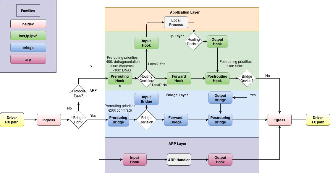
The following schematic shows packet flows through Linux networking:
Netfilter hooks, ref: https://wiki.nftables.org/wiki-nftables/index.php/Netfilter_hooks
With just the ability to add chains to tables and rules to chains, programs and users can control traffic with a high degree of configurability. Let’s explore a program docker.
apt-get update && apt-get install docker.io -y
With docker installed we can list all of the rules for any table:
iptables -t filter -L -n -v
Docker is controlling the IP address generation and assignment. When we add more containers with the following command, we will see he additional rules required to forward traffic to them:
#RUN FROM SOURCE
for i in {8001..8003}; do docker run –restart always -d -p $i:5678 hash iptables -t nat -L -n
On the nat table we can see additional walls created for these containers: lower three are correlating with the applications just created. With iptables we have an ability to direct or reject traffic as necessary.
#RUN FROM DESTINATION
curl networking-foundations-src:8001
curl networking-foundations-src:8002
curl networking-foundations-src:8003
We can reject the tcp traffic destined for prot 5678 on this host by replacing the first rule in the DOCKER-USER chain:
#RUN FROM SOURCE
iptables -R DOCKER-USER 1 -p tcp —dport 5678 -j REJECT
Running again the previous set of curl commands again should produce different output.
#Failed to connect to networking-foundation
Here is the rough outline of how traffic is parsed by iptables:
-
the traffic enters the PREROUTING chain
-
matches the only rule, which redirects to the DOCKER chain
-
which will match one of the DNAT rules, converting the ip and destination port accordingly
-
traffic then enters the FORWARD chain
-
matches the second rule, which redirects to the DOCKER-USER chain
-
and finally matches the only rule in this chain, which rejects any traffic destined for 5689 with tcp
We can confirm this behavior by auditing iptables– enabling tracing and sending a request:
#RUN FROM SOURCE
iptables -t raw -A PREROUTING -s networking-foundations-dst -j TRACE
xtables-monitor -t
Alternatively, we could create rules that accept specific traffic, return to a previous chain, drop the traffic, or even redirect to a subsequent chain.
Loadbalancers
iptables overlap the functionality between loadbalancers and firewalls, because you can interact the route between these services, and control the way they are routed.
There are many reasons why the traffic intended for a single destination might need to be distributed over multiple workloads.
-
reduce resource
- Requirements for single instances
-
improve performance
-
account for intermittent outages
-
test and compare the behavior of different configurations
The same as with the firewalls there are many solutions both physical and virtual. Some loadbalancing can be done with iptables configuration that distribute traffic on port 8004 across all three containers, but the traffic is not as even as the rules suggest.
For more control over how traffic is distributed to separate instances we will need to leverage IP Virtual Server or ipvs.
Ipvs uses some of the same kernel technology as iptables (netfilter), but is specifically designed for traffic distribution and can be more performant. We can distribute traffic with ipvs following the methods below:
-
round robin (second iptables example)
-
weighted round robin
-
least-connection
-
weighted least-connection
-
locally-based least-connection
-
locally-based least-connection with replication
-
destination-hashing
-
source-hashing
Make sure to delete iptables rules with iptables -t nat -D flag, so we don’t create overlapping rules conflicting one with another.
#RUN FROM SOURCE
iptables -t nat -D PREROUTING 1
iptables -t nat -D PREROUTING 1
iptables -t nat -D PREROUTING 1
Install ipvs utilities with:
#RUN FROM SOURCE
apt-get install ipvsadm -y
We can recreate our iptables round robin rule with following command:
#RUN FROM SOURCE
export ip=$(hostname -I | awk ‘{print #1}’)
echo “
-A -t $ip:8000 -s rr
-a -t $ip:8000 -r 172.17.0.2:5678 -m
-a -t $ip:8000 -r 172.17.0.3:5678 -m
-a -t $ip:8000 -r 172.17.0.4:5678 -m
” | ipvsadm -R
Ipvsadm
Instead of chains and tables, we create a service and apply configuration and destinations to it. Running this command should report an even distribution of endpoints:
for i in {1..100}; do curl -s networking-foundations-src:8000; done | sort | uniq -c
33 8001
33 8002
34 8003
Now each one of the containers corresponds to each one of the ports.
Let’s clear the service and try another distribution algorithm.
#RUN FROM SOURCE
Ipvsadm –clear
echo “
-A -t $ip:8005 -s wic
-a -t $ip:8005 -r 172.17.0.2:5678 -m -w 1
-a -t $ip:8005 -r 172.17.0.3:5678 -m -w 1
-a -t $ip:8005 -r 172.17.0.4:5678 -m -w 98
” | ipvsadm -R
Ipvsadm
# Most of the traffic will be routed to the fourth container.
for i in {1..100}; do curl -s networking-foundations-src:8005; done | sort | uniq -c
1 8001
1 8002
98 8003
With “weighted least connection” traffic is sent to the instance currently holding the least connections, but with a preference to those instances with higher numerical weights.
It is worth noting that in addition to the distribution algorithms, that ipvs also supports the following methods of forwarding:
-
direct routing (–gatewaying)
-
tunneling (–ipip)
-
and nat (–masquerading)
ipvs definitely has more to offer than loadbalancing domain than iptables did, but it too has limits. Between these two tools there is no way to make decisions on every protocol that may be leveraged within a network.
proxy
Modern applications often come with custom or niche demands that can’t be met by standard linux tools. This evolving set of demands is the foundation of a proxy.
A network proxy is some entity that receives and distributes the traffic on behalf of a client. Proxies leverage the capabilities we’ve mentioned along with several more for the use cases:
-
relaying different geolocation data than the original request
-
Anonymize source or destination information
-
in front of inbound or outbound traffic set firewall rules, authorization, authorization
-
encrypt and/or generally protect sensitive information
-
increasing the resilience
-
optimizing traffic flow
-
providing observability
Most traffic will probably travel through proxy at some point. Instead of common standards like iptables and ipvs, it is more common to consider the available tools as an ecosystem.
Specific proxies will suit certain use cases better than others.
If you’d like to explore some of the most popular options recommended:
-
envoy the backbone of Istio
-
haroxy the component of the RedHat OpenShift solution
-
nginx one common solution for exposing traffic in Kubernetes
Proxies are powerful in the domain of network transformation, security, and general optimization.
Container Networking through Networking Namespaces
Containers are isolated processes that run on a single operating system. Much like virtualization, containers will consume CPU, Memory, and Disk space, but require significantly less to run, as they are dedicated to a single function or a process. Any time a container is created a full operating system isn’t required.
A network doesn’t have to be created for every single container manually,- docker container runtime was first to create a workflow that allows it to get access to the network instantly. Kubernetes took this to another level and provided the Container Networking Interface (CNI).
Various Kubernetes environments such as Calico and Cilium work as a CNI communicating with the Kube API Server.
Since we’ve developed a ton of networking knowledge it’s worthwhile understanding how to build a networking namespace and have processes isolated to further understand containers and the associated networking.
Building a Networking Namespaces that communicate with each other
apt install net-tools
ip netns add sleep && ip netns add webapp
ip netns
ip netns exec sleep ip link
Ip netns exec sleep arp #IP address MAC
# each MAC is associated to an IP, but these endpoints in each namespace don’t know about each other. In Kubernetes each container that runs in a pod has its associated MAC address
ip netns exec sleep route
The best way to get to the outside from the physical interface of a host is to use the Linux bridge functionality. Previously we did route between two subnets in a private network, but to communicate broader, these network namespaces has to be exposed to the physical interface outside. It is like assigning an IP address to a process in its own namespace, or even, assigning an IP to a container that allows for all three to communicate with addressing in the same broadcast domain and subnet.
Let’s create one bridge and then present on the host.
ip link set dev app-net-0 up
create virtual interface namespace and end of the link that gets attached to the bridge
ip link add veth-sleep type veth peer name veth-sleep-br
ip link add veth-webapp type veth peer name veth-webapp-br
assign interface to respected namespaces
ip link set veth-sleep netns sleep
ip link set veth-webapp netns webapp
Assign the end of the link to the bridge
ip link set veth-sleep-br master app-net-0
ip link set veth-webapp-br master app-net-0
assign IP addresses to the different links on each namespace
ip -n sleep addr add 192.168.52.1/24 dev veth-sleep
ip -n sleep link set veth-sleep up
ip -n webapp addr add 192.168.52.1/24 dev veth-webapp
ip -n webapp link set veth-webapp up
#assign an IP address to the bridge that will be the access point to the physical (host network)
ip addr add 192.168.52.5/24 dev app-net-0
# bring virtual side of the bridge up, network namespace has link on its namespace & bridge
ip link set dev veth-sleep-br up
ip link set dev veth-webapp-br up
ip netns exec webapp ping 23.285.0.4
ip netns exec webapp route
network is unreachable
Let’s fix it by iptables rule that allows us to NAT the 192.168.52.0 with an IP on the host that can communicate outbound.
iptables -t net -A POSTROUTING -s 192.168.52.0/24 -j MASQUERADE
ip netns exec webapp ping 23.185.0.4
network is unreachable
Add the default route
ip nens exec webapp route
ip netns exec webapp ip route add default via 192.168.52.5
sysctl -w net.ipv4.ip.forward=1
ip netns exec webapp ping 23.185.0.4
We’re overloading the physical interface by:
-
creating two network namespaces that represent two containers
-
each namespace has IP address associated with container
-
the namespaces that has access to the bridge
-
the bridge has access to the physical host
-
the host has access to the same network.

This configuration is the reason for having Container Networking Interfaces that automates the process when pod comes up, gains IP address and access to the host networks outbound and communicate to the outside
Kubernetes Networking
Kubernetes, referred to as k8s, is an open source tool that allows to orchestrate container based workloads over heterogeneous infrastructure.
In this virtual environment we already have access to the three nodes in the kubernetes cluster and all of the commands necessary to investigate the network.
kubectl get nodes
Each node is designated a block of IP addresses from which it can assign pods and services. Each node is assigned to /24 or 254 usable IPs., which interfaces we can also see by command
ip a
Intra and Inter Pod Networking
Creating a single pod with two containers by applying the following yaml.
Kubectl apply -f <<EOF
apiVersion: v1
kind: Pod
metadata:
name: example-pod-1
labels:
app: example
spec:
nodeName: k8s-server
containers:
- name: container-one
image: gcr.io/intio-release/app/1.13
ports:
– containerPort: 8080
args:
– –port
– “8080”
– –grpc
– “9080”
– –tcp
– “10080”
– name: container-two
…
EOF
This pod is scheduled to our current host, so we can inspect it from inside and outside it’s network namespace.
All kubernetes clusters have a local dns service that is available through an IP in the service CIDR and loaded into every container
Now verify newly created pod and lookup the IP address of the nameserver:
kubectl get pod example-pod-2 -o wide
Three search domains are listed as well as IP address of the name server. Our search domain in particular default.svc.cluster.local follows the format <
In this example we leveraged first search domain and determined the IP address associated with that fqdn.
Upon calling that IP address, IPTables will intercept the request and load-balance the traffic among the available pods.
To see what each container has for interfaces:
kubectl exec example-pod-1 -c container-one – ip a
kubectl exec example-pod-1 -c container-two – ip a
To see some of the rules using:
Iptables -L –table nat | grep “example-pod-1”
As more pods are added, each additional pod will be added to the chain with a decreasing fractional probability.
With Kubernetes Control Plane and Node Components traffic within our cluster can now be made resilient and automatic.
